
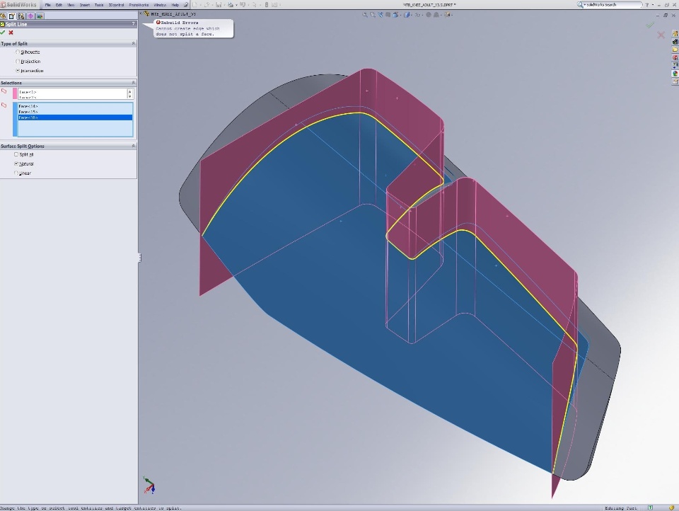
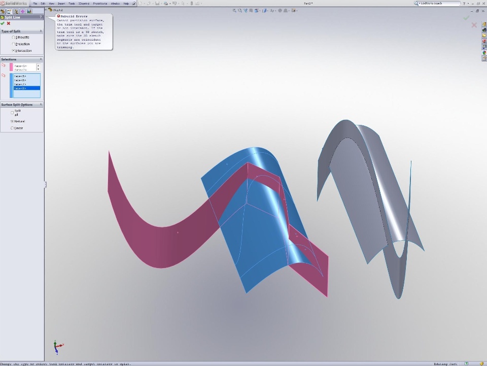
When I try to create a split line feature using a surfaceintersection, I get an error 99% of the time. Almost every time itsays, "cannot create an edge which does not split a face".Occasionally it says "trim tool and target are notintersecting....blah blah" even though they most definitely are.
I have to add 3-4 features to work around this every time, which isunacceptable. I use my workaround 4-5 times daily, at a minimum.
I had this problem about 25% of the time in 2008, and it has gottenworse since then. I cannot recall if this has ever worked in 2009.I am on 2009 sp 2.1.
What bugs the most is that one may clearly see that the surface isfully intersecting, but SW can't figure it out.
After some testing, I have narrowed this bug down to 1 case: whenboth the tool and target surfaces have more than one face, splitfails every time. If either tool or target is a single face body,the split will work. Otherwise, one must select one face on thetarget body per split feature, which is cumbersome and inefficient.Since very few of my surfaces have only one face, this bug bites meevery time I need a surface split.
I attached some images for this, as well as a sample part file withsome arbitrary surfaces. Try to split the multi-face pair, and tellme what happens!SolidworksSurfacing


I have to add 3-4 features to work around this every time, which isunacceptable. I use my workaround 4-5 times daily, at a minimum.
I had this problem about 25% of the time in 2008, and it has gottenworse since then. I cannot recall if this has ever worked in 2009.I am on 2009 sp 2.1.
What bugs the most is that one may clearly see that the surface isfully intersecting, but SW can't figure it out.
After some testing, I have narrowed this bug down to 1 case: whenboth the tool and target surfaces have more than one face, splitfails every time. If either tool or target is a single face body,the split will work. Otherwise, one must select one face on thetarget body per split feature, which is cumbersome and inefficient.Since very few of my surfaces have only one face, this bug bites meevery time I need a surface split.
I attached some images for this, as well as a sample part file withsome arbitrary surfaces. Try to split the multi-face pair, and tellme what happens!SolidworksSurfacing

I'm gonna guess that your results will improve if you select bodiesrather than faces. I can understand the face thing failing, becauseif you're selecting faces, SW doesn't know it's all one thingnecessarily, and the split line has to be continuous.
I can't duplicate your error, but I do get an error if I don't havefaces selected properly.
Just try to select bodies from the Surface Bodies folder at the topof the tree rather than selecting faces from the graphics window,or using the Filter Surface Bodies selection filter option. I'mguessing that this will work better and mean fewer picks to make itwork.
Matt's absolutely correct; make the selections using the Surfacebody folder so that you capture the entire surface body definition.Otherwise when using sketches (projection mode) its perfectly fineto pick from the screen.
Interesting. My examples do not reproduce the error if I selectbodies or any combination of bodies and faces. I will report if Ihave this issue with selecting bodies, as that is my preferredselection method whenever possible, yet I have run into this issuemany times. Your tips should save me some time; thank you!
Shaodun:
I'm running at 2048 x 1536. I cropped the screenshot so youwouldn't see the rest of my oh-so-interesting desktop.
In this example, I would only have to copy the face, split it, andreplace the original with the split faces. Not much, but still morework than I want to do for a simple split line.
ADIDAS...
All Day I Dream About Split...lines working?
Split..........Line..........Fails..........
Who at SW cares? My needle is pegged on nobody.
You're not the first one to lose his composure over this crap. Youcan beat your head til its a bloody stump, but that won't changeanything. Shaming SW into action won't work either. Been there,tried it, gave up.
The last example you show isn't fair. You've got a complex edge ona complex surface line to face and expecting it to split? You're anewbie, right? No way, I wouldn't do paid work like that. You haveto extend that red body a little where it intersects the blue.
There's two things you can do:
- cry yourself dry
- go get another surface modeler that works.
The second example, yeah, that's common. Why this obsession withSplit Line? Why not work in surfaces and use Trim? Both suck aboutequally, but with with trim you have other options.
You've gotta know some work arounds. You're simply naive if youexpect this stuff to do what you tell it to do.
The red body is tangent at the intersecting edge and as suchextending does not help. I should have stated that when I postedthe image.
Trim fails in this case due to geo. conditions, verification on. Ihave used surface bodies with the same results (or lack thereof).Again, I should have stated that when I posted the image.Alternatively, you could have pointed out my omission asked formore information.
You should know that I have workarounds. My previous posts statethis clearly.
I'm not sure why you re-phrased the last line of my previous postas if you were telling me something I did not already know. I willmake noise, and SolidWorks will hear it. Who at SW will listen? Myneedle is pegged on nobody. Are you offended that I am pointing outan area where I am failing to motivate SolidWorks into correctiveaction simply because you have failed and given up in that sameregard?
I have had this discussion with you before. My reasons for postingon this forum are twofold:
1. To increase my and others' knowledge of SolidWorks.
2. To provide feedback to SolidWorks when and if it is helpful
In my opinion this topic falls under both:
1. If there are workarounds I am not aware of, responses to thisthread may bring them to my attention.
2. This issue is clearly a limitation in SolidWorks; IF they care,they may do something about it. After all, the squeaky wheel getsthe grease. This is not to say that if I never started this topic,SolidWorks would never have known about it.
Your first post was clearly helpful. I thanked you because Iappreciate the valuable knowledge you have and your willingness toshare it with others. I look up to you as someone who has been inthe trenches, helping to make SolidWorks what it is today. Yourcondescension towards me is eroding that well-deserved respect. Iknow, you could just be having a bad day, but come on, mate! Atleast try to be helpful. I am not needlessly jamming the board byposting every time this happens; only when the suggestedworkarounds have started to run dry, so to speak.
You have attempted to illustrate my lack of composure whilebelittling my skills as a user of SolidWorks, and implying that Iam naive. This split line issue IS very frustrating for me, and Ihave done my best to draw upon my calmness of mind in order tosubstitute dry humor for frustrated expression. You don't need tohelp, or even laugh, but you don't need to be so rude either.
I could be absolutely wrong here, of course, but I'm just givingyou my thoughts on the matter
The example you show won't work because of the tolerance betweenthe edge of the surface body and the edge (or split line) on yoursolid body. You need to avoid these situations in SW because one isNon-manifold (open surface) and the other is manifold (closed body)and SW has a hard time distinguishing which side the resultantmaterial (Boolean) ends up on. Of course in the perfect CAD system,this shouldn't occur but this phenomen occurs in almost every otherCAD system to some degree depending on the absolute or relativetolerance of the part/system.. Why not make it a very hightolerance you might ask - if we did then that would take more ormuch more time to compute the result (the mathematicians call itparameterizing the boundary or edge) so we try to find a gooddefault tolerance to keep the performance up.
The classic case of this problem is when you create a sweptrectangular body along a somewhat swoopy spline. Then create asplit line on the top face of the swoopy rectilinear shape. Now usethat split line as the sweep path of a new surface who's profile isa simple 3 point spline - now try to cut away the rectilinear shapewith the newly created surface - it might work, it might not. If itdoes work, inspect the edge that used to be the split line. You'llprobably find that it is a "dirty edge" meaning that there are manysegments that are the original split line and then many other edgesthat are a result of the surface cut. They don't exactly coincidebecause of the tolerance of the sweep surface command and theoverall default tolerance of SW. I've attached a part as an exampleof how to use our heal edges command to clean up these dirty edges.
So In the image that you show where the red surface body isintersecting the blue solid part, just don't include the top faceof the solid and you'll be okay - that edge coinciding with thesurface body edge is probably why your split is failing.
I'm not sure what to do with the file you posted. I used thesupressed surface sweep to cut the solid, and indeed it generates abroken up "dirty" edge. When I try to heal these, SW says that theface has no edges that can be healed. Is that the point?
I should say that dirty edges are what motivated me to use a lessthan optimal split feature in this instance. All other methods Iknow about failed with verified rebuild on, and generated seriouslydirty edges with it off. I checked for invalid geometry, but therewas none to report. I used heal edges, but it altered the edge toomuch and the result was unnaceptable. What is worse, both thehealed edge and the unhealed dirty edge got even more jagged andeven partially lost tangency between its faces once mirrored!
Regarding the heal edge tool, I usually end up trying it, seeingwhat it does, and deleting it because it is too heavy handed andadjustments often do nothing. What I mean by that is that once Iclick on "heal edges", if I want to change a tolerance, I usuallyhave to rebuild and re-edit the feature, or build a new oneentirely. This makes it very hard to dial out the heavy edgehealing and simply "merge" tangent edges the way it would in aperfect world. An example of this is a 2-edge projected circularhole in an arbitrary surface. I have seen heal edges delete thehole, but usually it just goes way out of round. Sure, I can backoff my settings, but the featre doesn't update so well. I shouldadd that this is most common with imported geometry, but alsoappears with native geometry. To be fair though, heal edges hassaved me a few times and is always an option I at least try to use.
The top face of the solid body is already split at the intersectionof the red and blue bodies on the top face. I do not need to splitthat face. I tried selections of solid and surfaces, surfaces only,surfaces with surface faces, surfaces with solid faces, surfacefaces only, solid faces only (after thickening the split tool); Ieven copied the faces to split as an isolated body. I'm notsurprised that the final image I posted failed, but one of my otheroptions should have worked.
How possible would it be to make the system tolerances usercontrollable for a single session? I often need to max out theresolution slider in performance options just to get things towork. Some more headroom might be usefull, resources permitting.
Many Thanks,
and as Will asks could SW have an option to use a higher toleranceif the user desired? or does this make problems elsewhere?
someone with a faster pc might be happy to trade some performancefor better fits..
thanks for continuing to chat with users on the forum - we needmore like you here
..maybe even someone will answer my .net question over the comingyear
The heal edge default tolerances are pretty good and if they arechanged drastically it might be resulting in the things you'reseeing - I rarely change its values. It's for really, I mean reallymicroscopic edges; that's what it is best for - when I use it, itis usually on import parts that have problems. In fact, there was aforum user recently that had a file that you could not cut through.Turns out it was an import part from "another" surface modelingsystem. SolidWorks had imported it and put a solid import in the FMbut something was obviously corrupt about the body. Sure enough -heal edges on some adjacent faces in the model made things right.
Will, if you're just cognizance of the issues that you'veexperienced and things that you're learning and model in a way thatyou're not introducing "ambiguity" (i.e. surface body edges onother surface body edges - except in the case of knit of course)you'll be better off because not only will you be making bettermodels they will rebuild faster also.
Neil,
Our developers decide/set the default tolerance in SW from theparasolid kernel. We have never given the user the ability tocontrol it and I think that was the right decision. 12 years agowhen I was doing surfacing in ProE we did have the ability to setthe "relative" tolerance from the default ProE tolerance of .0012(don't ask me why I remember that number) It was great for bring inimport models that were really messed up or not exported correctly,but the down side is that once you got the model in you had tomaintain that part file at a custom model tolerance and that wouldmake regens go slower and the higher tolerance would actually causenew problems. Not to mention that once you were done with your workyou'd have to pass the file to others and now they'd have to dealwith the non-default tolerance built into the file - remember it'sall parametric/history based. Also another nasty result of relativemodel tolerance is that if you're building something really big,like the wing span of a Jet, and in the same part file try todimension the rivet hole to 2 places (inches) the feature willprobably fail.
I think this discussion about tolerance is important and valuable.Can you define what it really means? In manufacturing tolerance isthe distance from the theoretical "as designed" to the actual,based on some sort of datum reference.
In CAD models, what does tolerance mean? What is the datumreference?
In the Moi forum ( I trialled this recently) I saw a discussionabout how it had an accuracy of 0.005 and if a model was a largerone this messed up the boundaries.
Sounds much the same issue although I admit my CAD innards know-howis limited.
I guess this is related to the precision in windows and in respectof anything you might then want to perform - as in further featurecalcs - on the part afterward.
I wonder if this is any different if you use 64 bit rather than 32bit?
Could users still not be allowed discretion to use a 'highertolerance' setting in some instances? I am not sure what that mightmean - 5 or 10x?...
The file could be tagged as being so and flagged in the FM...
I am sorry I dont know enough to know whether a situation likeWill's should be worked around or whether it identifies somethingthat might be accomodated in SW programming
As Matt says it would be nice to know more about the tolerance.
This is some of the detail that typically doesnt make it to thehelp notes but assists people to understand what it is they arereally doing or why it doesnt happen
As far as tolerances go, making them adjustable ultimately affectsthe size of the model envelope available to build in. I believe nowthat the largest size model you can build in SW is 100 meters (orit could be 1000, I forget, but lets just say it's 100 forarguments sake). If you want to increase the tolerance by a factorof 10, then your model will now only be able to be 10 meters max. Itoo am a Pro-E user and we tend to run our models with a higheraccuracy than the default. This comes into play when you have smalldetails on a relatively large model that is based mostly on complexsurfaces. The thing about Pro-E is that is has two modes ofaccuracy: relative, and absolute. Relative is the default and is aratio of the diagonal measure of the model envelope. An examplewould be if you start with a small protrusion and put a holethrough it which is very close to an edge of it; then make anotherprotrusion off the side of that that is 100 times the size of theoriginal; then reorder that hole after the big protrusion, thathole may fail do to the accuracy actually changing on you as youmodel. Absolute accuracy is just that, set according to your modelunits and does not change with model size, but will affect howlarge a model you can produce. Parts that are merged into eachother (kind of like the combine command in SW) MUST have the sameaccuracy set.
Tell me if I'm wrong Mark B, but I believe SW accuracy is absolute(set relative to units and not model size).
Your "absolutely" right - SW uses absolute accuracy because we didnot want to deal with the issue of relative accuracy as does proein its default mode. Thanks for the ProE discription.
Currently the largest part model you can build in SW is 1000M.
We freed up the restriction from 2008 to 2009 in assemblies thou.Now you can assembly any number of 1000m objects to total more than1000m.
Will,
I read eagerly regarding possible work-arounds for split line,... I am relatively new at SW about 6 months now, and have
just recently had 2011 SP3 and simulation installed. All self taught, and it has been a steep curve,...
I find that in simulation - using split while loading surfaces reliably chokes SW, I need to use task manager to kill
the application because exit then fails,... This is really a crash. I do get an error window stating " the object invoked has disconnected from the client",
or something very similar to that. This is a Windows error I believe and demonstrates that SW has a good solid bug, nothing "sometimes" about it.
Probably a un-initailized pointer.
Maybe this is good so it will get some attention, I have sent in the report thru our VAR. It is troublesome to read that SW seems to ignore problems.
I have been searching for a work around. In the previous cases that I ran into this I was able to
build separate bodies in the part and un-check merge - the split point then revolves and breaks the surface.
However this strategy does not always work. I get the same crash like behavior if I add a sketch to the part
and use that instead of an intersect surface. I have spent many hours at it and I am hoping that there is a work around.
It seems to me that when two entities, say two circlular curves, or two lines meet which are colinear - then SW
simplifies the result into one entity. The reverse should happen if you use a split, one entity becomes two. My bet is that
the simplification or decomposition of two entities into one is not supressed when an explicit split is introduced.
Anyway - if you have alternate workaround ideas I would appreciate hearing.
Dan