
Hello,
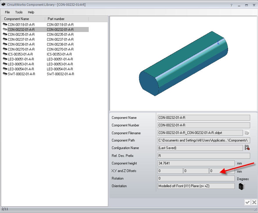
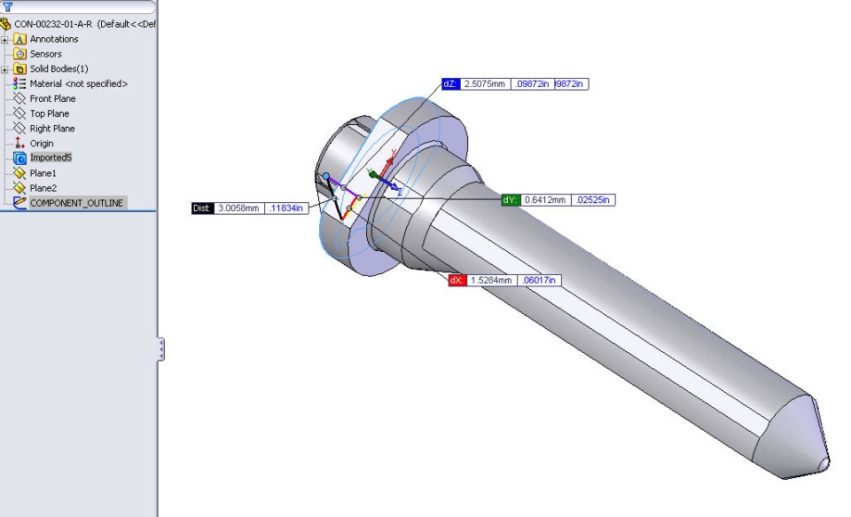
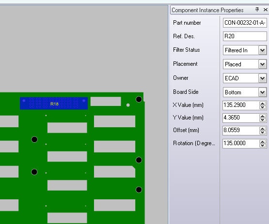
I'm new to SolidWorks and Circuits. I'm exporting a SolidWorksmodel to CircuitWorks and saving as IDF. I viewed the .emn file andnoticed some of the THRU-HOLE components have a non-zero offset(components placed on TOP and BOTTOM).
Why is there an offset when the component is mated flush to thePCB?
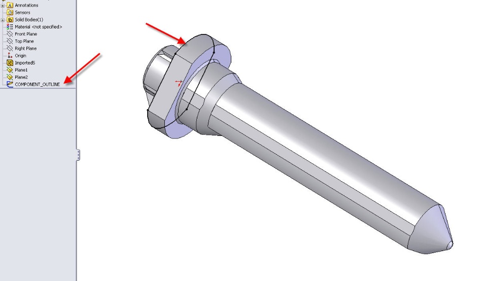
I experienced a similar problem using ProE, and the issue wasrelated to the REF_DES coordinate system was placed outside theMCAD model volume, i.e. a BGA component with the coordinate systemoffset from the substrate to account for the height of the solderballs. Thus the MCAD geometry was not is contact with the PCB.
Any help would be greatly appreciated :-)SolidworksCircuitworks
I'm new to SolidWorks and Circuits. I'm exporting a SolidWorksmodel to CircuitWorks and saving as IDF. I viewed the .emn file andnoticed some of the THRU-HOLE components have a non-zero offset(components placed on TOP and BOTTOM).
Why is there an offset when the component is mated flush to thePCB?
I experienced a similar problem using ProE, and the issue wasrelated to the REF_DES coordinate system was placed outside theMCAD model volume, i.e. a BGA component with the coordinate systemoffset from the substrate to account for the height of the solderballs. Thus the MCAD geometry was not is contact with the PCB.
Any help would be greatly appreciated :-)SolidworksCircuitworks
