
We need to solicit the opinion of our users to help us decideon how to proceed on a potentially longstanding, but for manyperhaps an obscure, issue pertaining to our chamfer feature.
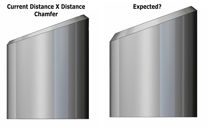
Currently a chamfer feature who's adjacent faces are not 90 degreesto each other or varying in angle of incidence to each other, andthe user specifies a distance X distance chamfer we give them aseemingly incorrect result. This is because we are using the"rolling-ball" technique of the Parasolid fillet and this does notactually calculate the distance, normal to the face, from theoriginal edge that was selected for the chamfer resulting width ofthe chamfer. (please refer to the images attached)
This is most predominant in non-machine parts where algorithmicfaces share a common edge and the angle of incidence between thefaces varies.
I have attached a part which has three configurations. The two thatI would like you to compare are the "Chamfer Feature" and"Expected" First make the view TOP and then click between the twoconfigurations.
So, I would like to know what you expect the result of a Distance XDistance Chamfer to produce on an example like the angled face ofthe cylinder.
Have we got it right and this is not an issue, or have we got itwrong and this has always been an issue that needs to be fixed?
For more information on this issue, go to the following thread inthis forumclickhere
Thanks
SolidworksParts And Features
