
We are trying to use a 3-line composite geometric tolerancefor the profile of a surface. When we do the first two lines, andselect the composite check box, it displays fine. When we add thethird line, as soon as we go to select the geo. tol. type with thedrop-down arrow box the composite check box grays out and the geo.tol. shows the following image, rather than one composite profiledistributed across all three rows.
Any ideas? This appears to be a bug.
SolidworksDrawings And Detailing

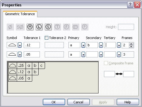






Any ideas? This appears to be a bug.
SolidworksDrawings And Detailing

You're absolutely correct. Sadly though, SolidWorks allows for asmany lines as you'd like (see attachment). And, of course, none ofthe information has to make any sense.
Scott, just so you don't get the wrong idea, this is not directedtoward you.
====> Slight Rant <===
There are countless CAD programs out there and no matter how goodone might be with a particular software package, it does not meanyou are a drafter, detailer, designer or whatever. What I see is alot of "CAD Jockeys" out there who don't even know the basics ofForm, Fit & Function, let alone how to properly toleranceparts, determine thread requirements, o-ring glands & fits,etc.
When you mention standards like:
ASME Y14.1 Decimal Inch Drawing Sheet Size and Format
ASME Y14.2M Line Conventions and Lettering
ASME Y14.3M Multi-view and Sectional View Drawings
ASME Y14.5M Dimensioning and Tolerancing
ASME Y14.6 Screw Thread Representation
ASME Y14.8M Castings and Forgings
ASME Y14.24 Types and Applications of Engineering Drawings
ASME Y14.34M Associated Lists
ASME Y14.35M Revision of Engineering Drawings and Associated Lists
ASME Y14.36M Surface Texture Symbols
ASME Y14.38 Abbreviations and Acronyms
ASME Y14.100M Engineering Drawing Practices
Most folks say one of two things,
"What?"
-- or --
"We don't follow those."
I've interviewed way too many people whose applications may listseveral CAD packages but when you ask them to do a simple drawing,they don't have a clue.
For the most part, this can be attributed to the places that teachCAD but only CAD.
So when it comes to the documentation tools provided by a CADpackage, like; Drawing Templates, Drawing Types, Views,Dimensioning, Tolerancing, GD&T, Surface Finishes, Welds,Datums, you name it, well, this seems to be Greek to them.
The bottom line is CAD is only a tool, a glorified electronicdrafting board if you will.
CAD can be an "Aide" but it will not properly design & documentproducts for you.
I've never seen that ASME limits the number of segments orprohibits a mix of tolerance types, so I can't see how any CADpackage could prevent the sort of mess that you show in yourattachment. I thought it was pretty good that Solidworks got thecomposite control frame right.
[If you wonder how a person like me is a COSMOS User Group leader,ask me for that strange story.]
Well, a determined attitude & a willingness to learn will getyou just about anywhere you want to go and a little luck doesn'thurt.
My advise to anyone in your position would be to seek out those youwork with to mentor you in the different aspects of your work. Agood designeer, an engineer and a machinist are invaluable peopleto surround yourself with.
I taught a SW course about a month ago and one of the gals I hadin class had some trouble when we got to the basics of assembles.When I mentioned Concentric & Coincident as two of the mostcommon mates, she said, "What does concentric mean?"