
Hi, I am relatively new to Solidworks Simulation and just wanted to check and see that what I am doing is acceptable.
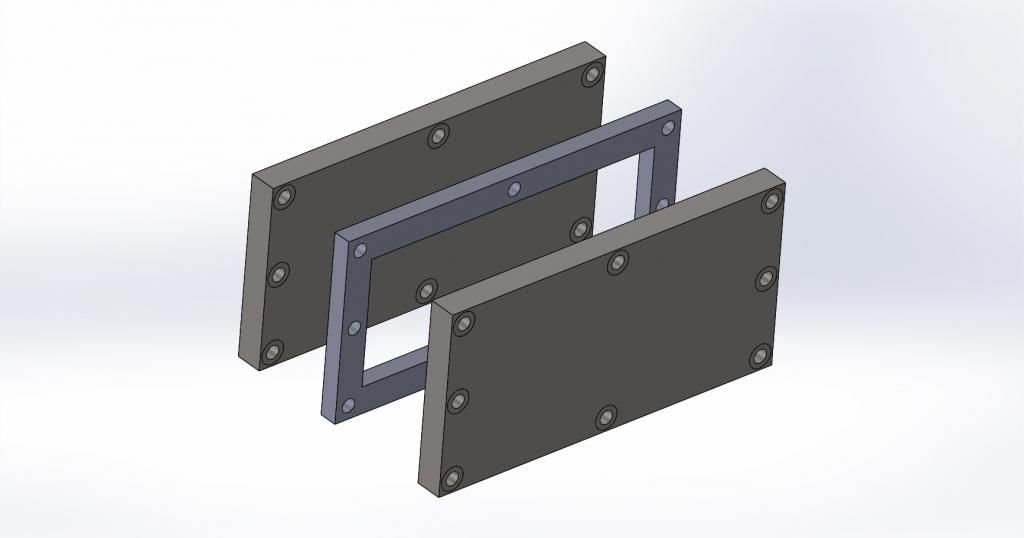
The design I am working with involves a rectangular plastic frame sandwiched by two steel compression plates. The plates and frame have the same length and width dimensions. Compression is achieved by 8 bolts spaced around the perimeter of metal plate, which go through the entire assembly and are secured by nuts where they exit out from the other plate. The bolts are torqued to a specific value.
I am trying to optimize the design of the metal plate. Currently it is 3/4" thick and very heavy. Definitely overkill. I want to put it on a diet, and make it thinner. Here's where the simulation comes in!
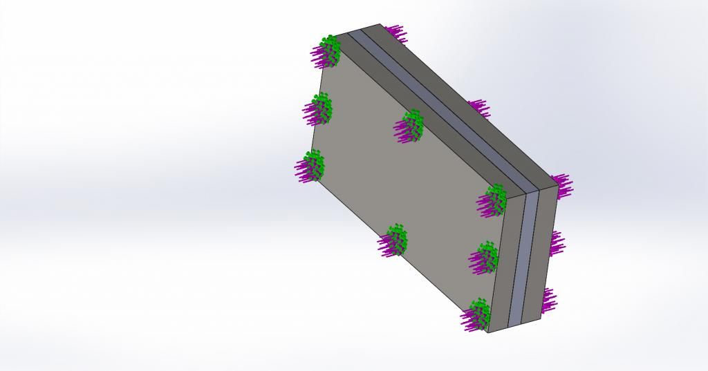
I am unsure of the proper way to fixture this. I made split lines on the metal plate, which simulate the diameter of a washer and would be where the compressive force is applied to the plate. I used these split lines for the fixture (fixed geometry) of the assembly, only on one plate. I them applied force to them with external loads, on both plates. I used "per item", since each bolt is applying its own force.
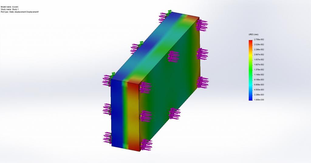
Is there a better way to fixture the assembly? I'm not sure how realistic that is, because it probably does/could deform in the location of the bolts under too much load. The fixed geometry would not allow this though, correct? It seems to effect the results in the plots. I would expect a symmetric result, but the plate with the fixed geometry is largely blue and the one without fixturing is red/yellow/green (in the displacement plot).
Attached are pics of a simplified assembly to get my point across.
Exploded view showing the two plates, and frame:
http://i154.photobucket.com/albums/s270/connorburke/Eos/Exploded_zpsffa9dde5.jpg
Showing fixturing on one plate only, and applied loads (Set to "per item")
http://i154.photobucket.com/albums/s270/connorburke/Eos/forces_zps28a80f98.jpg
Showing results, I would suspect symmetric coloring...I think my fixturing is incorrect.
http://i154.photobucket.com/albums/s270/connorburke/displacement_zps1d2e673b.jpg
Thanks for any advice, tips or help!
Connor
SolidworksSimulation