
Do you know, you can create Curves from Equation in the 3DEXPERIENCE CATIA.
For example these beautiful Epicycloid curves were created using following parametric equations:
x = (a + b) sin(t) - b sin((a/b + 1) t)
y = (a + b) cos(t) - b cos((a/b + 1) t)
This power can be used for more than just creating pretty curves.
This post shows the application of this power in solving engineering problems. Here we have outlined the method of
- creating the cam profiles
- creating the assembly and cam mechanism
- analysis to determine the velocity and acceleration at various position of the follower
Problem:
Create a 3DXML file to generate radial CAM and follower profile according to the given input:
- Base circle radius of the disc, r
- Maximum height of the follower, h
- Motion of the follower: Simple harmonic motion (SHM) or Constant velocity
also plot displacement, speed and acceleration plot of follower motion.
Workflow:
Create CAM
- Open Part Design App
- Edit the 3D Shape
- Go to Tools section of the Action bar
- Select the Formula command and create following parameters
- Follower motion, type: String)
- r, type: Length
- h, type: Length
- th, type: Angle
- In the Tools section, Expand the secondary area of the group of commands by clicking the arrow next to the separator
- Select the Law command to create three laws x, y & z to generate the CAM profile.
- Note: Create formula parameters of length type and real type, in each law.
Code:
Law: x
if `Follower Motion` == 'SHM'
{
if 180deg*t
if 180deg*t Law: y
if `Follower Motion` == 'SHM'
{
if 180deg*t
if 180deg*t Law: z
z = 0*t
- Open Generative Shape Design App
- Go to Wireframe section of the Action bar
- Open the flyout menu of the Spline command and select Curve from Equations
- Note: If the cure is not visible, then activate Action Bar > View > View Modes > Wires
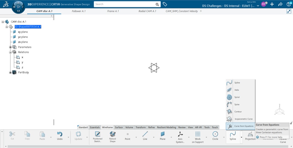
- Select corresponding laws for X, Y & Z as input.
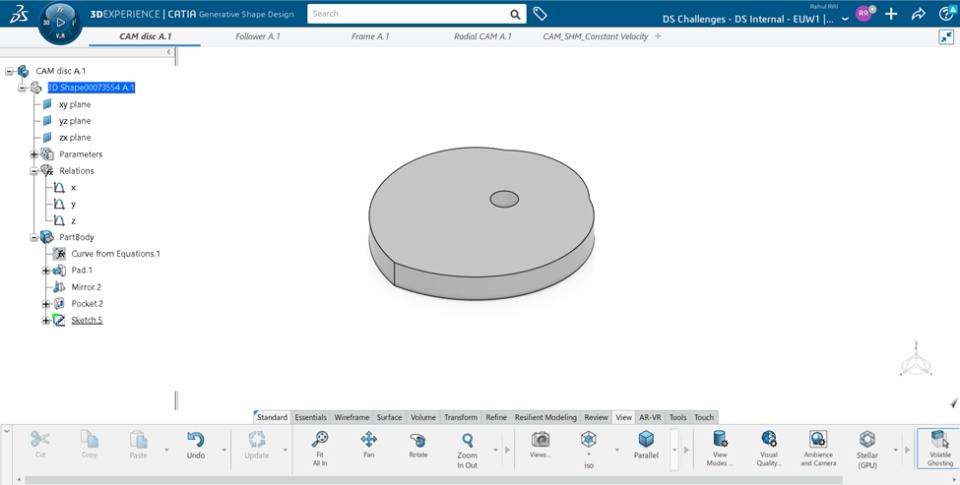
- Switch to Part Design App
- Create a Positioned Sketch in a plane parallel to the plane of the curve
- Project the curve in the sketch using Project 3D Elements and draw a line to create a close the profile.
- Go to Model section of the Action bar
- Select the Pad command and create a pad of appropriate thickness.
- Go to Transform section of the Action bar
- Select Mirror command and mirror about the flat surface.
- Create a circular Pocket or Pad, at the centre of the base circle to attach it with the frame.
- Create a Positioned Sketch on the flat face of the cam disc and project the cam profile using Project 3D Elements
Create a follower
- Create a follower of appropriate dimensions
- Create a point at the contact point of the follower and the cam disc (in this case, origin)
Create a frame
- Create a frame according to appropriate dimensions
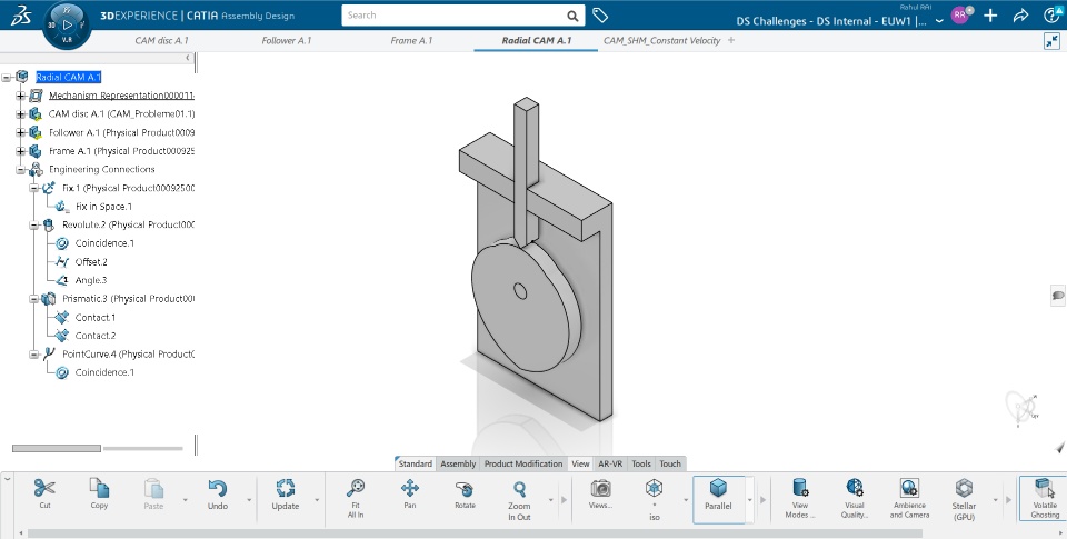
Create Assembly
- Create a Physical Product
- Insert the Cam Disc, Follower & Frame, and orient them properly
- Apply Fix Constraint to the frame
- Create a Revolute joint between frame and the cam disc
- Create a Prismatic joint between follower and the frame
- Create a Point and curve joint between contact point of the follower and the profile sketch of the cam disc
Simulation and Analysis
- Open Mechanical Systems Design App
- Go to Mechanical Systems Design section of the Action bar
- Create a mechanism using Mechanism representation command
- Test the motion using Mechanism Player
- Open Mechanical Systems Experience App
- Create a Simulation Object
- Go to Scenario section of the Action bar
- Create a Law Excitation
- Select the revolute command of the mechanism as Support
- Angle Formula: Angle = `Excitations\\Law Excitation.1\\Time` *100deg/1sec
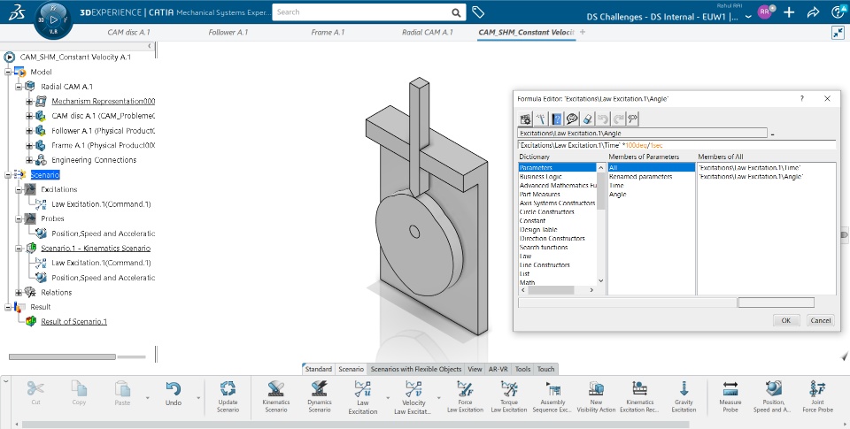
- Add a Position, Speed and Acceleration Probe at the contact point of the follower and the cam disc.
- Create a Kinematics Scenario with
- Excitation:
- Law Excitation
- Probe:
- Position, Speed and Acceleration
- Parameters:
- Start Time = 0s
- End Time = 3.6s
- Step Time = 0.05s.
- Select Compute and Generate Results
- Select View Scenario Results
- Select appropriate data and switch to Plot tab to view the graphs.
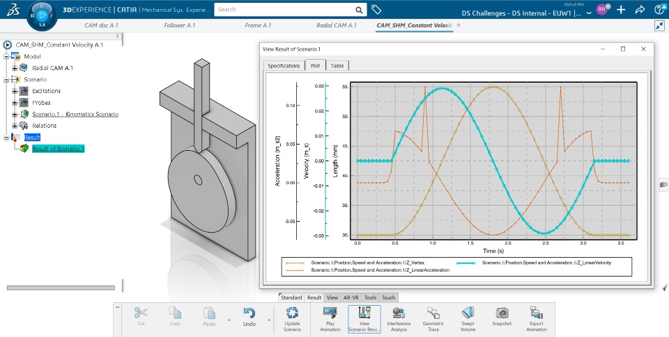
Simple Harmonic Follower Motion 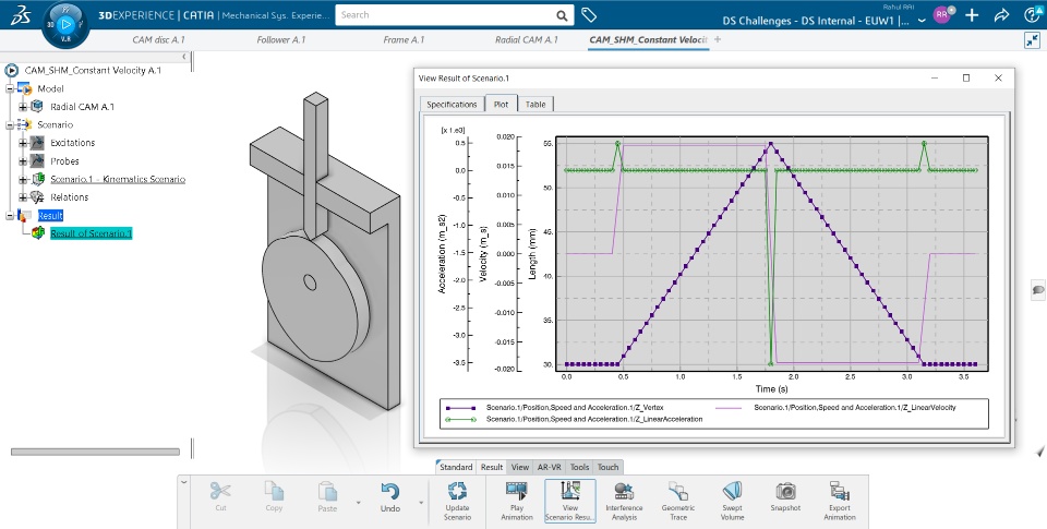
Constant Speed Follower Motion
Downloadable 3DXML
Preview


Simple Harmonic Motion (SHM) 
Constant Velocity Motion
💪Powers of Generative Shape Design App
✅ quickly model shapes using wireframe and surface features
✅ large set of tools for creating and editing shape designs
✅ can be combined with other apps to preform solid-based hybrid modeling.
To know more click here: User Assistance >> 3D Modeling >> 3D Modeling Core >> Generative Shape Design
💪Powers of Mechanical System Design(MSD)
✅ Contact (⭐ friction, collision, etc.)
✅ Gravity ⭐
✅ Axial Spring
✅ Bushing
💪Powers of Mechanical System Experience(MSE)
✅ Position Excitation
✅ Velocity Excitation
✅ Force Excitation
✅ Torque Excitation
✅ Sequence of Excitation
✅ Probes (⭐ position, speed, acceleration, joint force, etc.)
✅ Plots
✅ Traces
Courses:
Perform as a Mechanical and Shape Designer
Practice CATIA Mechanical Systems Design
Practice CATIA Mechanical Systems Experience
Certification:
3DEXPERIENCE Mechanical Motion Designer - Associate
Download and use more Mechanisms
Edu Part Design Assembly Design Generative Shape Design Mechanical Systems Experience
